Analysis Examples
Solver Magnetic Field Analysis ELF/MAGIC ≫
The following calculation times are on a Core i7 6700K PC (in seconds).
Halbach array magnet (linear shape)
Calculation time: < 1 second
This is an example of spatial magnetic field calculation with magnets arranged in a Halbach array (linear shape).
A strong magnetic field is obtained on only one side of the magnet.
Halbach array magnet (ring shape)
Calculation time: < 1 second
This is an example of calculating the spatial magnetic field by arranging magnets in a Halbach array (ring shape).
Create two pairs of these magnets and place them opposite each other.
Calculation time: 8 seconds
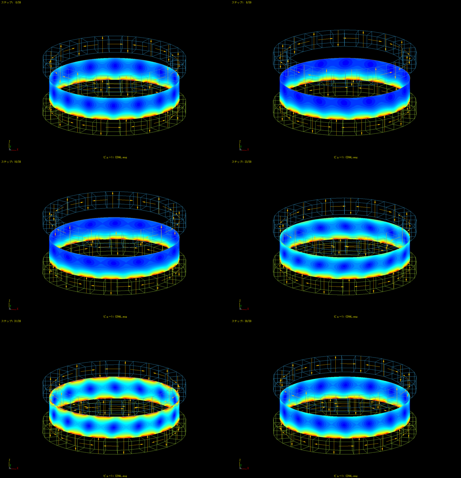
This is an example of moving a magnet up and down while rotating it.
T-type magnetic material
Calculation time: < 1 second
This is a calculation of the spatial magnetic field created by a magnet and four magnetic materials.
The spatial magnetic field can be calculated with only 5 material elements.
Ring shaped magnet
Calculation time: < 1 second
The spatial magnetic fields around a ring-shaped magnet are calculated.
The magnet has only 24 divisions of elements.
The enlarged image on the right shows that the magnetic fields are accurately obtained to the vicinity of the magnets even when coarse elements are used.
Actuator
Calculation time: 16 seconds
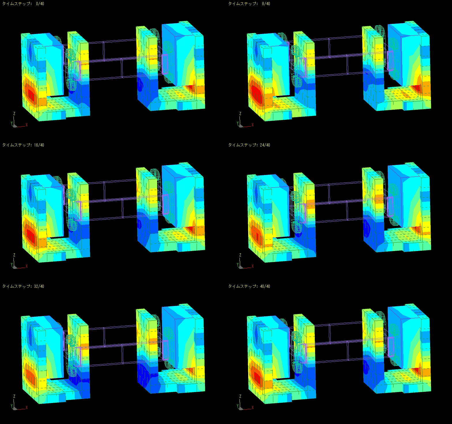
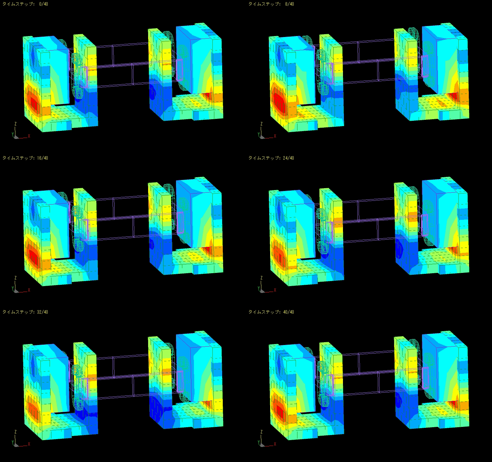
This is an example of magnetic field analysis of an actuator.
Analysis is performed while moving the mover.
Linearity analysis can be performed by calculating the forces acting on the coil.
IH
Calculation time: 7 seconds
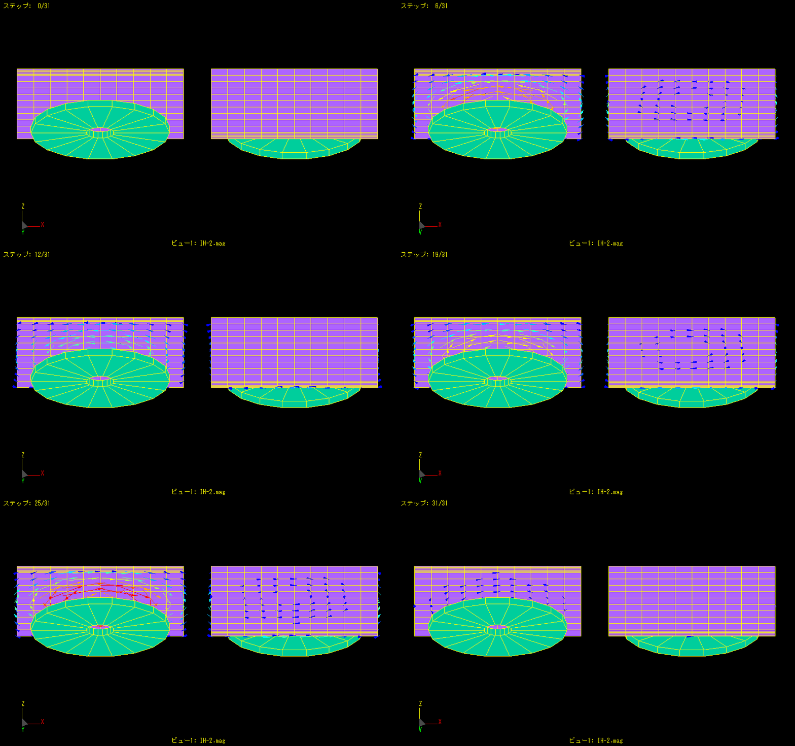
High frequency is applied to a disk-shaped coil to generate eddy currents in a nearby metal plate.
The left figure shows the coil side and the right figure shows the opposite side.
More eddy currents flow on the metal plate close to the coil, but fewer eddy currents are generated on the back side.
Thus, the penetration thickness of eddy currents can also be analyzed.
Damped Vibration Analysis of Magnet
Calculation time: 22 seconds
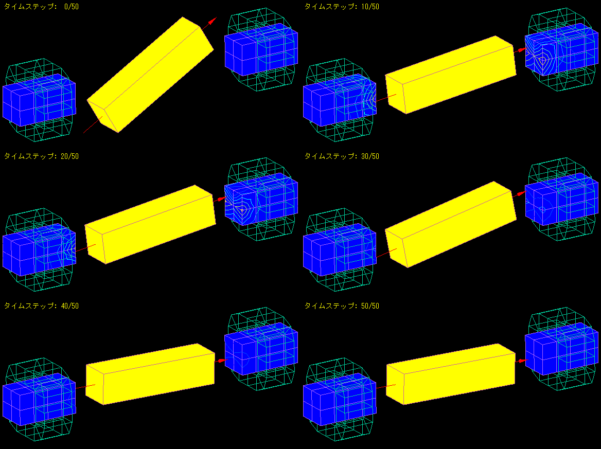
A magnetic body with a coil wound around it is placed on both sides of a bar magnet.
When the magnet is attached with the center of the bar magnet as the axis of rotation, the bar magnet begins to move like a pendulum as its magnetic poles are attracted to the magnetic body.
We analyzed how the amplitude of the oscillation is damped by the induced currents in the coil and the eddy currents in the magnetic body.
Current Sensor
Calculation time: 8 seconds
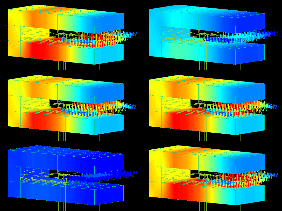
The spatial magnetic field at the core gap is analyzed by flowing the current through the gap of the " C " shaped core.
By varying the current, the linearity of the spatial magnetic field can be checked.
Analysis can be easily performed by changing the core geometry and the position of the current flow.
Proximity sensor
Calculation time: 4 minutes 4 seconds
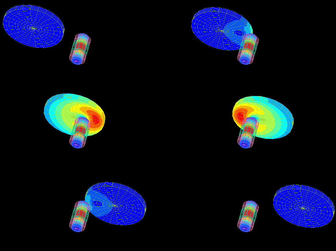
This is an example of proximity sensor analysis.
An alternating current is applied to the excitation coil, and the change in the induced voltage generated in the detection coil is examined.
When a disc-shaped metal plate passes in front of the sensor, the output of the detection coil changes due to the eddy currents generated in the metal.
The figure shows the contour of the eddy current density generated in the disk.
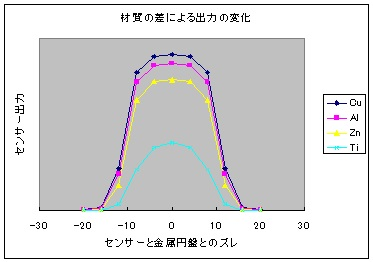
The graph shows the change in sensor output for different metal materials.
Aluminum Sorting Machine
Calculation time: 66 seconds
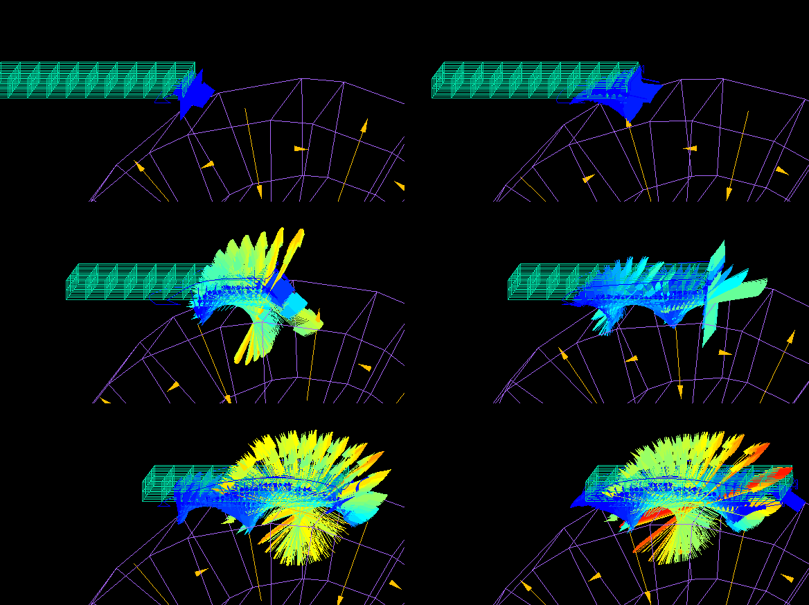
This is an example of analysis of the force received on an aluminum plate in an aluminum sorting machine.
The alternating magnetic field generated by the rotating magnetic drum causes eddy currents flowing through the aluminum plate, which exerts a force on the aluminum plate.
This force is calculated using Maxwell's stress surfaces created by surrounding the aluminum plate.
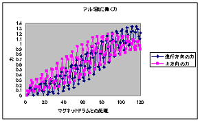
As the aluminum plate approaches the rotating magnet drum, the forces acting in the forward and upward directions increase.
(The magnet array of the magnetic drum is a Halbach array.)
Next, we examined the kinematic state of the aluminum by changing its shape to that of a disc.
(The equations of motion are embedded in a VB script to calculate them.)
Repeat the following steps (1) through (5).
(1) Calculation of MAGIC.
(2) Extraction of the force received by the aluminum disk.
(3) Calculate the position and velocity of the aluminum disk.
(4) Prepare for the next MAGIC calculation.
(5) Return to (1).
Calculation time: 13 minutes 30 seconds

The aluminum disk pops forward and upward while rotating, and then falls.
(Aerodynamic drag is also taken into account in a simplified manner.)
The force due to eddy currents is always taken into account, even while rotating and falling.
(A 300-step calculation is thinned down to every 6 steps to be displayed.)
Relay
Calculation time: 15 seconds
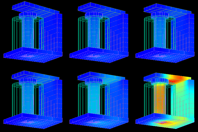
We analyzed the magnetic circuit by moving the movable iron core of an electromagnetic relay (electromagnetic relay).
Since no space elements are required, the movable iron core is moved until it is in close contact with the fixed iron core.
Calculation of force is also easy. Furthermore, calculations that take eddy currents into account are also possible.
Dependent magnetic wheel
When the magnet is rotated near the edge of the conductor plate, the torque distribution in the direction of rotation is biased and a thrust component is generated.
A repulsive force (levitation force) is also generated between the magnetic wheel and the conductor.
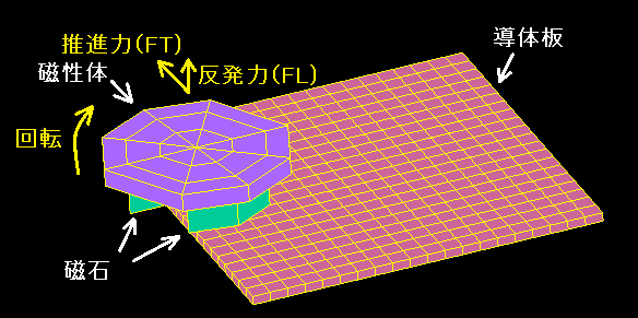
Changing the distance "dy" between the center of the magnetic wheel and the edge of the conductor plate also changes the thrust and repulsive force.
Calculation time 1: second per STEP, 216 STEP.
The figure is for the latter 72 STEP.
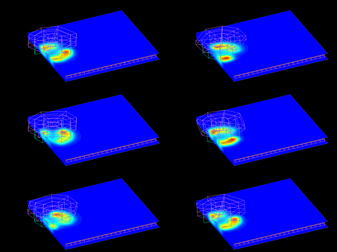
This is a contour plot of the force at dy = +20.
The following graph compares the measured data with the analysis results.
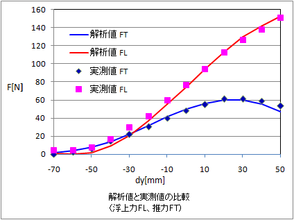
Analytical values are obtained with a high degree of accuracy.
It is also easy to analyze the rotation of the magnet while moving the conductor plate.
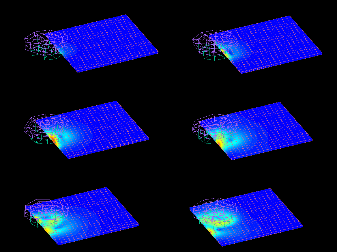
Contour map of eddy current density.
Permanent Magnet Rotation Type Eddy Current Magnetic Levitation System
Multiple magnets are arranged in a row and rotated at high speed where they float slightly above the copper plate.
The magnets are arranged in a Halbach array.
The actual calculation is performed using the 1/5 model.
Calculation time : 5 seconds (80 seconds total).
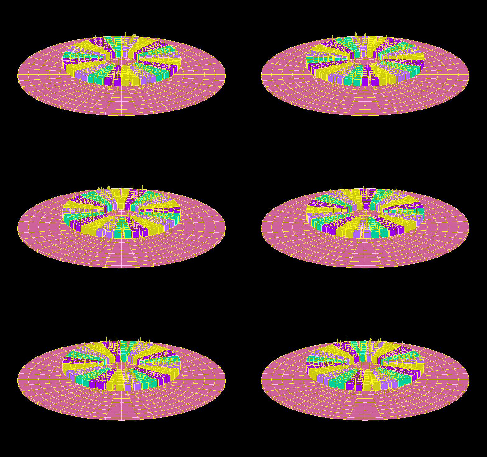
The eddy currents generated in the copper plate and the magnetic force of the magnets cause the magnet group to be subjected to an upward repulsive force. (Magnetic levitation)
We compared the measured and calculated values of magnetic levitation force by changing the number of revolutions and the distance between the copper plate and the magnet group.
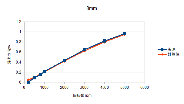
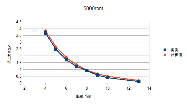
Details are available in 電気学会研究会資料 静止器・回転機合同研究会 SA-18-22,RM-18-22
TEAM Problem 7
Testing Electromagnetic Analysis Methods (T.E.A.M.) Problem 7.
Calculation time: 45 seconds
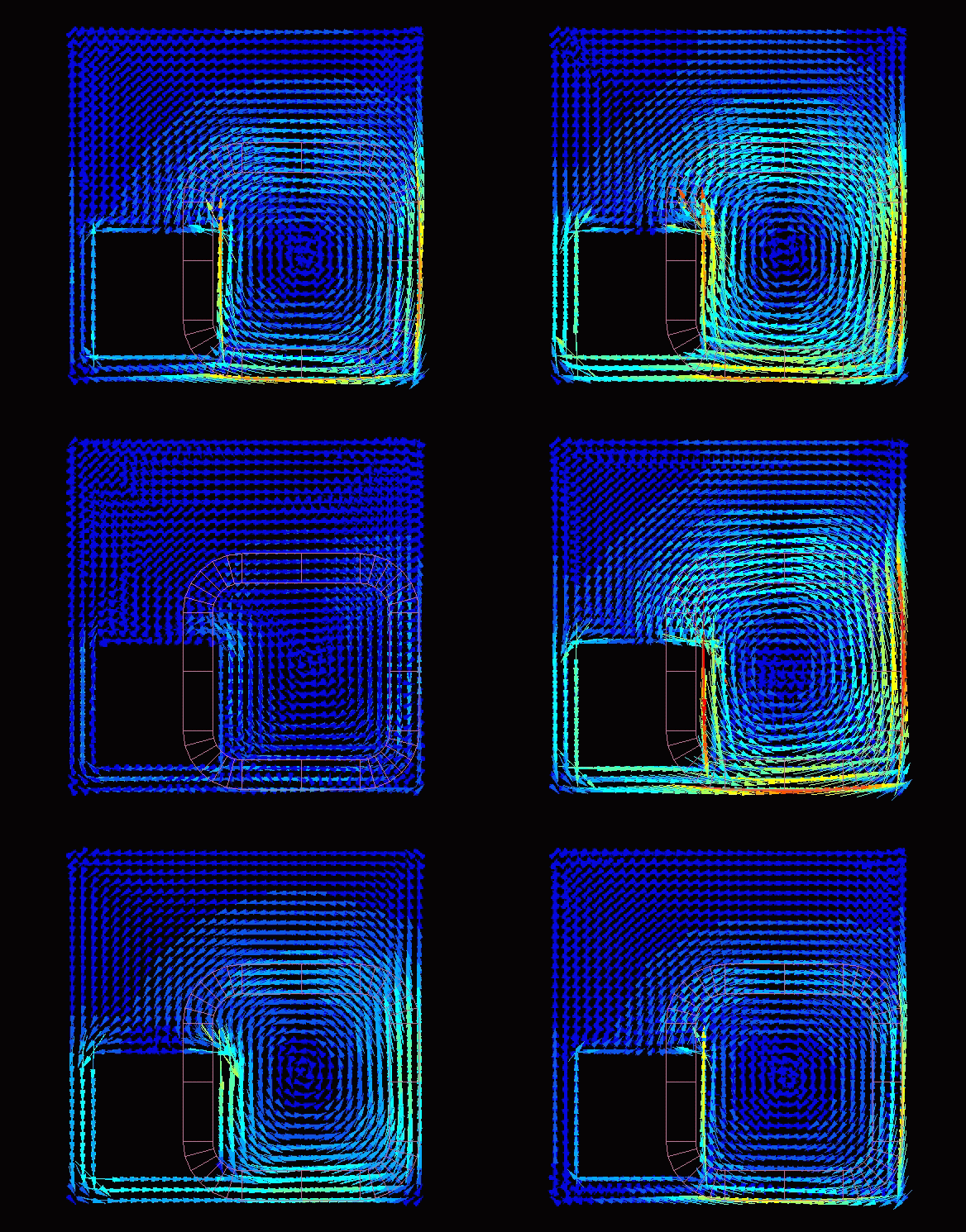
This is the flow of eddy currents. The natural flow is simulated.
We coarsened the elements a bit more. With this division of elements, the calculation time was 2 seconds.
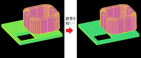

The magnetic flux density of the space. It matches well with the actual measurement even when the elements are coarsened.
TEAM Problem 13
Testing Electromagnetic Analysis Methods (T.E.A.M.) Problem 13.
Three magnetic elements are placed around the coil with gaps between each other.
The overall view is shown with the mesh used in the calculations.
During the analysis, the model is solved with a quarter model to take advantage of the symmetry.
Calculation time: 7 seconds
The magnetic flux density of the magnetic material was calculated and shown in a contour plot.
The magnetic materials are slightly shifted across the gap, and the way the magnetic flux flows is somewhat complicated.
The average magnetic flux density at each cross section of the magnetic material was calculated and compared with the measured value.
It matches well with the actual measurement.
TEAM Problem 20
Testing Electromagnetic Analysis Methods (T.E.A.M.) Problem 20.
This model consists of a center pole made of magnetic material, a yoke, and a coil.
There is a gap between the center pole and the yoke at the top and bottom.
Calculate the spatial magnetic field of the gap and the force acting on the center pole by varying the coil current (1000AT, 3000AT, 4500AT, 5000AT).
Calculation time: 32 seconds
This is a quarter-model mesh, magnetic flux density vector, and flux density contour map of the magnetic material.
The spatial magnetic field Bx of the upper gap was calculated and compared to the measured value.
Good agreement is observed for both 1000AT and 5000AT with different degrees of magnetic saturation.
The forces acting on the center pole were calculated and compared with actual measurements.
It can be seen that the change in the degree of magnetic saturation due to the increase in current is reflected in the change in force.
TEAM Problem 24
Testing Electromagnetic Analysis Methods (T.E.A.M.) Problem 24.
In a magnetic circuit consisting of a stator, a rotor and a coil, the problem is to calculate the transient response of various characteristics until 0.3 seconds after the rotor is fixed at a 22-degree angle and a voltage of 0 V to 23.1 V is applied to the coil.
The inductance of the coil and the effect of eddy currents generated in the magnetic material are also taken into account.
Calculation time : 1 minute 20 seconds/step
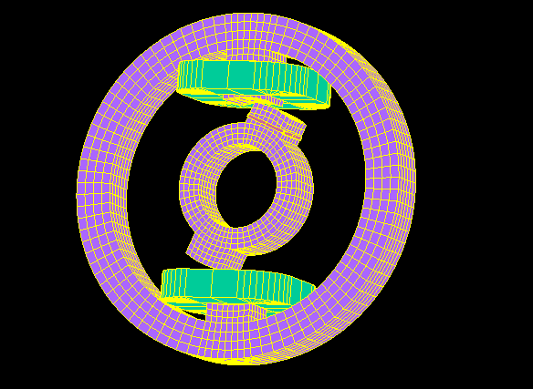
This is a mesh of the overall geometry and calculations.
(The symmetry was used in the analysis to compute the 1/4 model.)
The magnetic flux density near the gap between the stator and rotor.
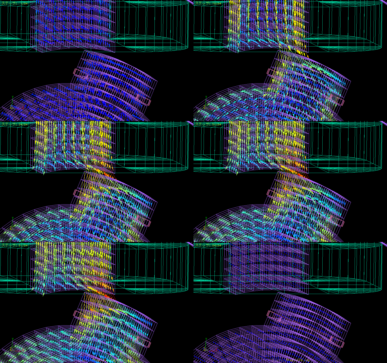
It does not change much from about 50 steps (0.1 second after voltage was applied).
Transient response graphs of coil current, spatial magnetic field, search coil interlinkage flux, and torque.
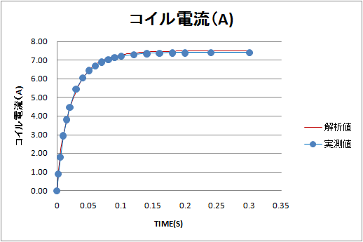
This is the change in the current flowing through the coil.
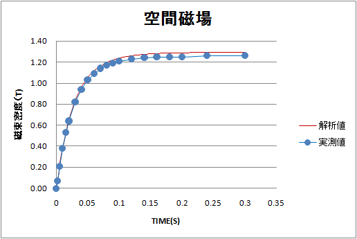
The spatial magnetic field change in the vicinity of the specified gap.
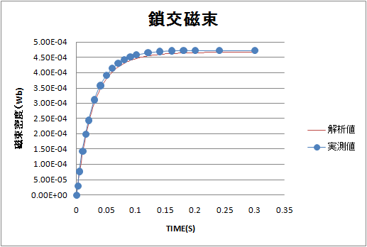
This is the change in the magnetic flux chained to the search coil.
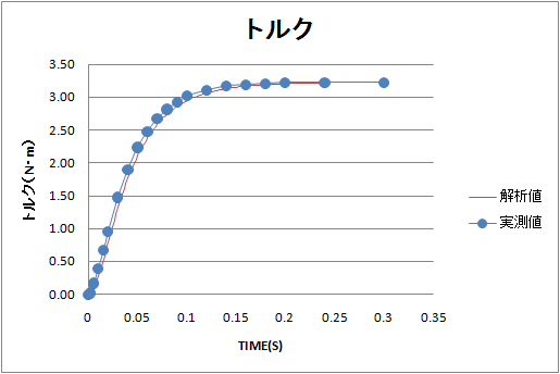
It is the change in torque acting on the fixed rotor.
The actual calculation is for 150 steps, assuming one step is 0.002 seconds.
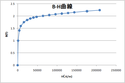
This is the B-H curve used in the calculation.
Brushed DC motor
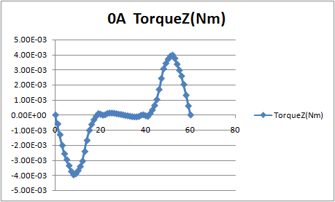
Rotor rotates one revolution without applying current to the coil.
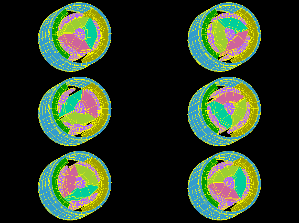
Calculate the cogging torque and the magnetic flux chained to the coil.
From the interlinkage flux, the no-load speed can be obtained.
Calculation time: 5 minutes 30 seconds
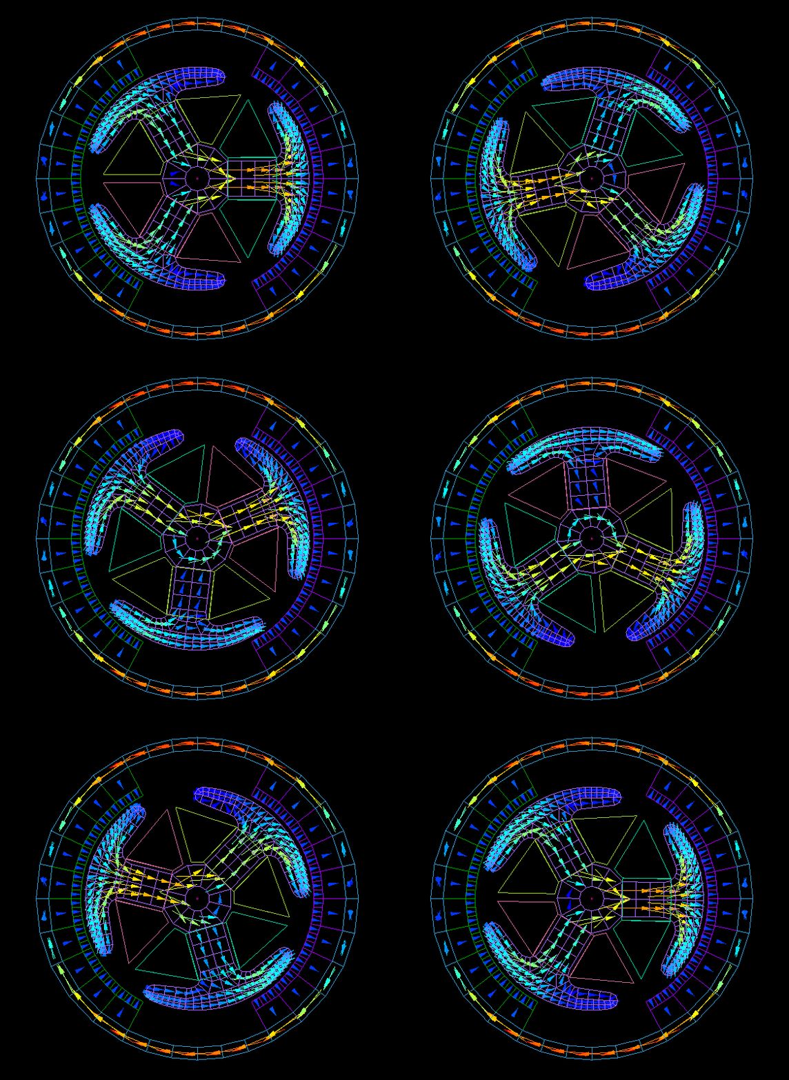
The actual calculation is done in 1° steps over a 60° region due to its periodicity.
Graph of cogging torque.
At no-load rotation, the
1. The drive voltage to the motor is balanced by the induced voltage generated by the motor.
2. The induced voltage is determined by the interlinkage flux of the coil and the number of rotations.
The no-load RPM can be obtained from the relation
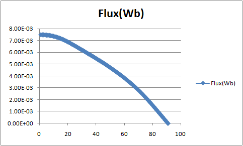
(The 90° portion is created from data of multiple coils for the 60° portion.)
Revolution speed (RPM)=(drive voltage/interlinkage flux)×(60/2π)
In the case of this model, the interlinkage flux is 7.32 mWb, so if the drive voltage is 3 V, the no-load speed is approximately 3900 rpm.
Next, determine the starting torque.
The torque is calculated by applying current to the motor and making one very slow rotation.
The result is calculated by assuming the resistance of the coil to be 3Ω and applying a current of 1A from a drive voltage of 3V.
Calculation time: 3 minutes 50 seconds
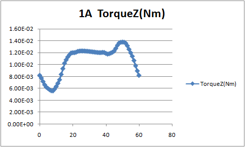
It can be seen that the starting torque is approximately 10.8 mN-m.
stepping motor
This is an example of analysis of a claw pole PM motor.
This is a claw pole PM motor with 16 claw poles each for the AB-phase coils.
The model is created with one-eighth symmetry.
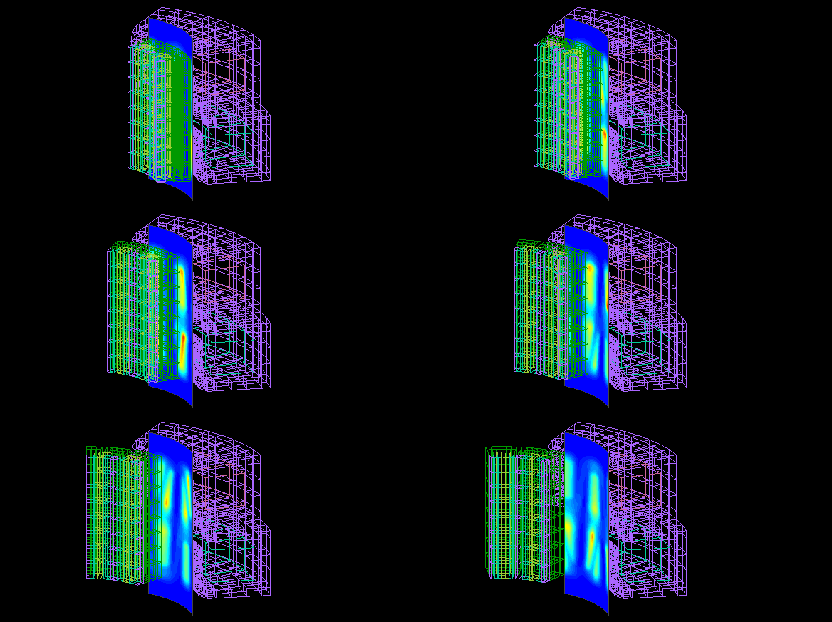
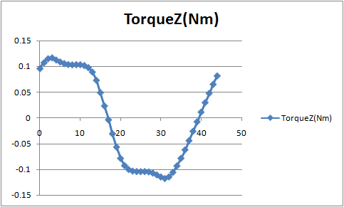
Calculated in 45 steps of 1° each without current flow in the coil.
Calculation time : 6 minutes 25 seconds
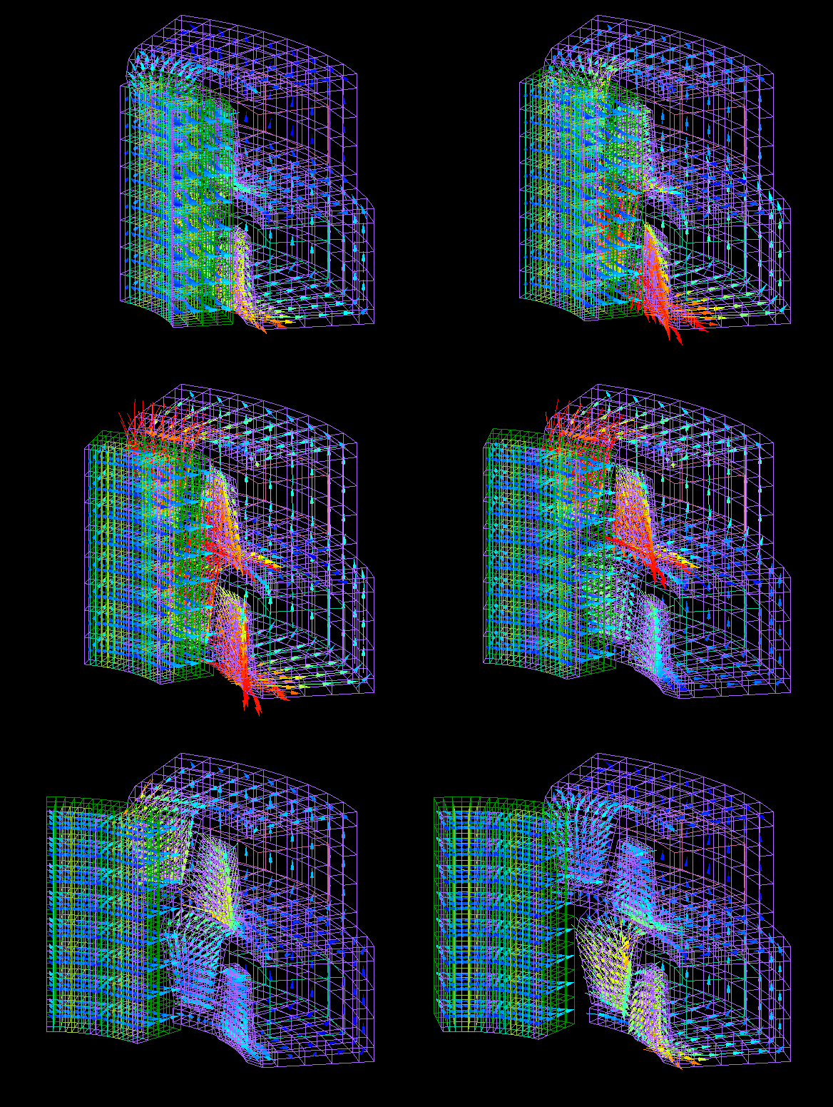
The magnetic flux density.
The detent torque, a static characteristic of stepping motors, is calculated on Maxwell's stress surface.
Calculation time : Above + 1 minute 8 seconds
This is the relationship between rotation angle and torque.
Example problems that can be calculated in the demo version
Examples can be found in the (ELFGuide) in (6 SampleGuideMAGIC).
a:33715 t:1 y:0
